AECOsim Building Designer Help

Conceptual Design

Used to quickly create preliminary building designs and executing energy calculations and simulations to analyze the proposed building's energy performance. Conceptual Design creates a simple Energy Simulator project; a building with floors, rooms, glazing, thermal zones and HVAC systems, and provides the ability to change aspects of concept building to simulate varying design scenarios.

Opens when creating new Energy Simulator projects or opening DGN files that are not valid Energy Simulator files and selecting the AES Conceptual Project option provided on the Create AES Project dialog.

Project Location

The Conceptual Design dialog opens to the Project Location tab by default. Here you enter basic project information for the building and the building location.


SettingDescription
Building Information Contains settings used to enter basic information about the proposed building including units and unit format.
  • Units - Used to select between IP-Imperial and SI-Metric units systems for the project. The units system selected here persists throughout the user interface where units are displayed.
  • Units Format - Used to set the units format using the IP-Imperial units system. The options allow you to display values using either decimal or fraction formats. Units Format is disabled when the project units are set to SI - Metric.
    Tip: Units Display – Units are displayed using the default system of units that was defined for the project, but can be changed to display using alternative units.
  • Project - Used to enter a name for the project.
  • Engineer - Used to enter a name for the engineer who is in charge of the project.
  • Building - Used to enter a name for the proposed building.
Location Information Contain settings used to define the proposed building location and select the weather profile nearest to the building location as well as the building orientation and the climate and moisture zone classification.
  • Continent - Used to select the continent in which the proposed building site is located. By default, the continent property is determined by the settings in the Defaults Manager dialog box. Use the drop-down list to select the continent applicable to your project site. The continent selection made here filters the Country drop-down list to display only the countries located on the selected continent.
  • Country - Used to select the country your proposed building site is located. The selection made here filters the State/Province drop-down list to display only the states or provinces located in the selected country.
  • State - Used to select the state or province your proposed building site is located. The selection made here filters the Location drop-down list to display only the weather locations found in the selected state or province.
  • Location - Used to select the nearest weather station to your project site.
  • Weather profile - Used to select from a list of weather data profiles that are located near the conceptual building site.
  • Climate/Moisture Zone - Used to set the climate and moisture zones in which the project site is located. Climate zones are specified with a number (1 through 8) and moisture zones, a letter (A, B or C).

    The 2006 International Energy Conservation Code (IECC) Climate Zone map of the continental United States of America

  • Orientation - Used to set the orientation of the building. Orientation refers to solar orientation which is the siting of the building with respect to solar access. The orientation value entered here defines the angle between the building y-axis and true north in the clockwise direction. A rotation of 180 degrees flips the building around so that the north (or back) facade is facing south (or front).Orientation has an impact on heating, lighting and cooling costs. By maximizing southern exposure, the building design can take advantage of the sun for daylight and passive solar heating. This results in lower cooling costs by minimizing western exposures, where it's most difficult to provide shade from the sun.

Model Creation

Contains tools and settings used to model the proposed building.

SettingDescription
Geometry Contains tools and settings used to create a mass model of your proposed building using common AECOsim Building Designer solid modeling tools.
  • Trace Room opens the Trace space which is used to define the overall building shape (floor plan) when creating a Conceptual Design.


  • Place Cone opens the Cone Solid tool which is used to place a solid cone.
  • Place Slab opens the Slab Solid tool which is used to place an extruded solid with a rectangular cross-section.
  • Place Cylinder opens the Cylinder Solid tool which is used to place a solid cylinder.
  • Modify Solid opens the Modify Solid Entity tool which is used to manipulate faces, edges, or vertices of a solid by pushing or pulling them interactively.
  • Unite Solid opens the Unite Solids tool which is used to unite two or more overlapping solids.
  • Number of edges for cylinder sets the number of edges to be used for creating zones (Rooms) that follow the cone's curved surface.
  • Show solid - When on, displays the solids used to design the proposed building along with the energy model. When off, only the energy model is displayed.
  • Create Building creates the energy model Building object. The Project Tree is populated with the Building object.
Floor Data Contains settings used to define floors and specify the number of floors in the building and the individual floor heights.
  • Number of building floors defines the number of floors in the building. The building height is divided by the number of floors to determine the floor heights.
  • Floor details displays the floor name (defaults to Floor0, Floor1, Floor2,etc) in editable fields.
  • Floor height displays the floor height for each floor in editable fields.
Ext. Shade Contains settings used to select and apply external shading or fin definitions to your proposed building.
  • Fin Type - When on, fins are added to the building. When off, no fins are added to the building and fin settings are disabled.
    • Fins - Used to select a fin type for placement. The Fins drop-down list contains all the fin assembly definitions available to the project.
  • Fin Manager opens the Fin Manager which is used to manage fin data contained within your project or at the application level.
  • Overhang projection (% window height) defines the amount of recess shading on the glazing as a percentage of the overall height of the glazing band.
  • Pick facade - Click to manually select the building facades to apply the fins to.
  • Global - Click to apply the fins to all the building facades.
Glazing Contains settings used to apply glazing to the proposed building by entering a percentage or ratio for the entire building or a specific facade.
  • Glazing percentage defines the amount of glazing (windows) area as a percentage of the total outside surface area of each building floor. A band of glazing will be created around the outside walls of each floor.
  • Pick facade - Click to manually select the building facades to apply the glazing to.
  • Global - Click to apply the glazing to all the building facades.
Skylights Contains settings used to add a skylight to your proposed building by entering a size or percentage.
  • Include skylights - When on, a skylights are included with the building. When off, no skylights are included with the building and skylights settings are disabled.
  • Skylights size (W x L) - Enter the skylight width and length values in the two adjacent fields. The value field uses active units but can be changed with the units drop down options.
  • Target % area - Enter an overall percentage to define skylights.
Zoning Contains controls used to define the thermal zones in your proposed building.
  • No zoning is used when no additional zoning work is needed to conceptualize the building. When selected, sets up the conceptual model with the default zones created whenever a floor is added, essentially one zone per floor.
  • Manual zoning is used to create a single zone on each floor, to which additional zoning work can be done with virtual walls.
  • Auto zoning is used to create both outer zones and one inner zone for each floor. Each outer zone is in contact with the exterior surfaces of the building, and its depth is defined with a setback distance. The shape of the building determines how many outer zones are created. There is always only one inner zone.
  • Perimeter zone depth (enabled for Auto zoning) determines the depth of the inner zone boundary by defining a setback distance from the outer surfaces of the building. A default value is provided that is proportional to the size of the traced building shape, but it can be changed.
Update model Applies all changes to the energy model, and populates the Project Tree.
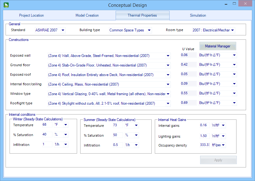
Thermal Properties

Contains settings used to define thermal properties of your proposed building.

SettingDescription
General Contains settings used to define the default calculation standard and the default building and room types to be used for the proposed building.
  • Standard
  • Building type - Used to select from a catalog of building types. Energy Simulator provides two building type catalogs based on the calculation standards from ASHRAE and CIBSE. The default calculation standard is defined in the Buildings Defaults.
  • Room type - Used to select from a list of room types whose properties are applied to the rooms created for the conceptual building. Room types are determined by the Building type selected.
Constructions Contains settings used to select from a catalog of material constructions to define the proposed building's surfaces.
The available constructions are:
  • Exposed wall
  • Ground floor
  • Exposed roof
  • Internal floor/ceiling
  • Glazing type
  • U Value displays the U-Value for selected constructions. The U-Value comes from the fabric data associated with the material constructions.
  • Units displays the U-Value default units which can be changed.
  • Material Manager opens the Materials Manager which is used to view, create, modify and edit building constructions and materials.
Internal conditions Contains settings used to define the thermal design parameters used for energy calculations and simulation.
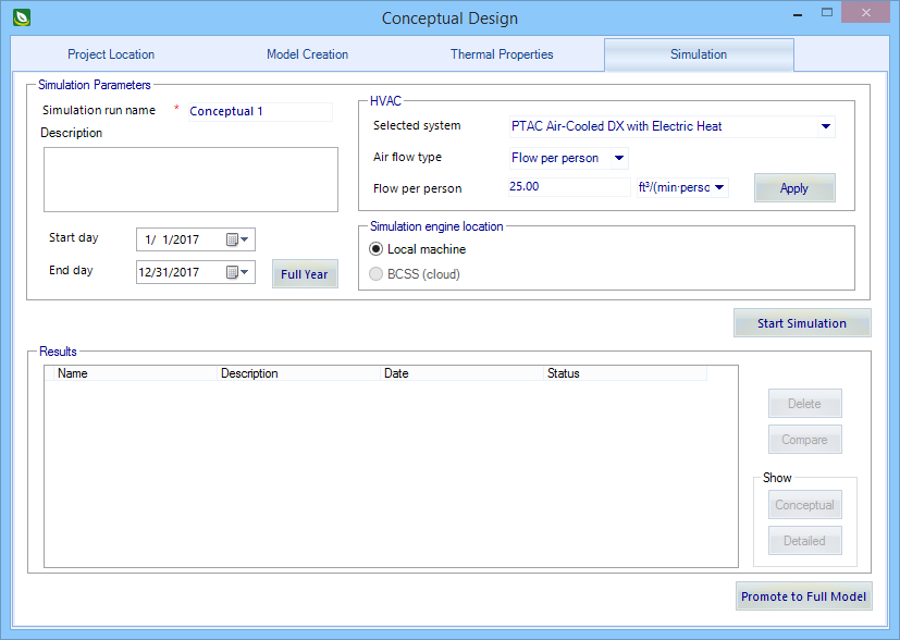
  • Winter
    • Temperature - Sets the design temperature to be maintained.
    • & Saturation - Sets the saturation percentage required to initialize humidity control during heating.
    • Infiltration - Sets the number of air changes per hour produced by outdoor air flow into the zone from window/door openings and cracks in the exterior surfaces. The value displayed here is the minimum supply air volume rate to be maintained for peak heat loss load conditions.
    Note: Infiltration rates entered here are handled as an arithmetic average in steady state calculations.
  • Summer
    • Temperature - Sets the design temperature to be maintained.
    • & Saturation - Sets the saturation percentage required to initialize humidity control during heating.
    • Infiltration - Sets the number of air changes per hour produced by outdoor air flow into the zone from window/door openings and cracks in the exterior surfaces. The value displayed here is the minimum supply air volume rate to be maintained for peak heat loss load conditions.
    Note: Infiltration rates entered here are handled as an arithmetic average in steady state calculations.
  • Internal heat Gains
    • Internal gains - Defines an internal gains value to apply to each room created for the conceptual building. Room internal gains are attributed to other heat sources in the room.
    • Lighting gains - Defines a lighting gains value to apply to each room created for the conceptual building. Room lighting gains are attributed to lighting that infiltrates into the room.
    • Occupancy density - Defines an occupancy density value to apply to each room created for the conceptual building. Room occupancy determines heat gains attributed to the number of people occupying the space.

Simulation tab

Contains settings to run multiple energy simulations and compare results for the proposed building using different durations and HVAC systems.

SettingDescription
Simulation parameters Contains settings used to "setup" simulations by defining parameters such as the simulation duration (date range for any calendar year), the HVAC system, design airflow and type, and options to run the simulation locally on your system or on the cloud.
  • Simulation run name - Used to enter unique names for simulations.
  • Start Day - Used to select start dates for simulations.
  • End Day - Used to select end dates for simulations.
  • Full Year - Click to simulate an entire year.
  • HVAC
    • Select system - Select from a list of HVAC systems which can be applied with no additional steps or interactions. The list of HVAC systems is a subset of the HVAC systems available in the HVAC Manager. As soon as an HVAC system is selected, it is added the conceptual design project, and HVAC system components are added to the Room object hierarchies in the Energy Simulator Project Tree.
    • Air flow type - Contains controls used to select which air flow calculation method to use for simulations. When one is selected, a corresponding method value field is enabled.
      • Flow per person - When selected, the air flow calculation method used is a factor per persons occupying the room. A flow rate must be entered for the Flow rate per person control which is enabled by this selection.
      • Flow per room - When selected, the air flow calculation method used is to directly enter the design volume flow rate for the room. A flow rate must be entered for the Flow per room control which is enabled by this selection.
      • Flow per area - When selected, the air flow calculation method used is a factor per floor area of the zone (room floor area is calculated as a portion of the total zone floor area). A flow rate must be entered for the Flow per area control which is enabled by this selection.
      • Air changes per hour - When selected, the air flow calculation method used is the number of air changes per hour for the infiltration amount. The infiltration amount must be entered for the Air changes per hour control which is enabled by this selection.
    • Apply - Used to apply the changes made in the simulation parameters to the energy model.
  • Simulation engine location
    • Local machine - When on, simulations runs are done on the local machine, and BCSS (cloud) is disabled.
    • BCSS (cloud) - When on, simulations runs are done on the cloud, and Local machine is disabled.
    • BCSS configuration opens the Cloud Configuration dialog which is used to sign in and run simulations on the cloud.
Start simulation Used to start simulations after the proposed building is modeled. Once started, simulations appear in the Results table.
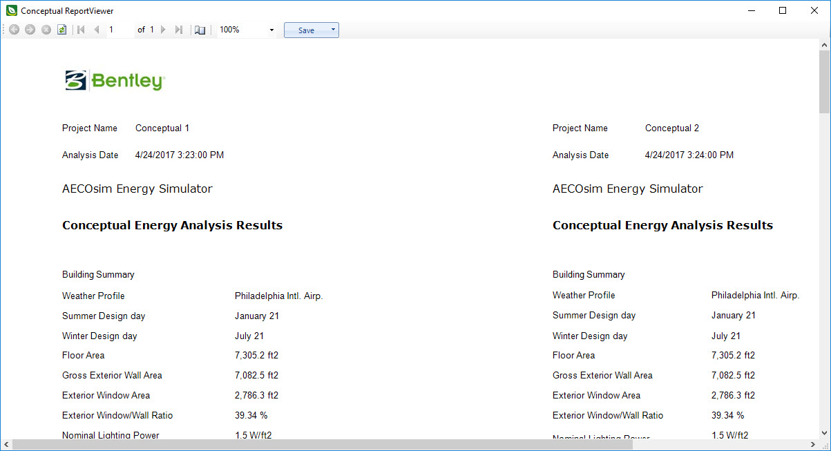
Results Contains settings used to review and compare results from simulations using different Simulation parameters. Both conceptual and detailed simulation results can be opened to review and generate reports.
  • Simulations - Simulations are listed in the table. Use the " + " control to expand the simulation to view its status.
    • Name - Displays the unique name given to the simulation.
    • Description - Displays a description associated with the simulation.
    • Date - Displays the date the simulation run was completed.
    • Status - Displays the status of the simulation (ie "complete", "running")
  • Delete - Used to delete selected simulations.
  • Compare - Used to compare simulations. The button is enabled when a minimum of 2 simulations are listed. Clicking Compare opens the Conceptual Report Viewer dialog displaying Used to provide information about the selected report. the Report details settings group appears when a saved simulation is selected.
  • Conceptual opens the Conceptual Report Viewer dialog.
  • Detailed opens the Runtime Details of simulation result. If any error occurred in the simulation processing, an additional "Error Report" tab appears next to it.
Promote to full model Promotes (upgrades) the conceptual model to a fully functional Energy Simulator project DGN, and closes the dialog.